Test motorcycle tps sensor Throttle position tps bosch connector webhelp maxxecu sensors 1.7 l throttle position sensor circuit board (4 pin connector)
2001 Vulcan 1500 Wiring Diagram - Wiring Diagram
Throtle body wiring diagram 💥 throttle position sensor wiring diagram 👈 Throttle position schemas sv650 diagrams
26+ toyota tps wiring diagram
Circuit diagramGm accelerator pedal position sensor wiring diagram Pin wiring diagram ecu wiring ecu basic diagram bike any switches wire6 pin throttle position sensor wiring diagram.
Tps wiring sensor throttle position chevy location repair diagram 1990 ecm wire diagrams astro terminal body color 1995 engine changedThrottle position sensor problem? Throttle position sensor explanation for wiring diagram[diagram] 1998 vulcan 1500 wiring diagram.

Vulcan kawasaki wiring streak
Ford throttle position sensor wiring diagramFord throttle position sensor wiring diagram Carburetor wiring diagramThrottle position sensor.
Pin on diagrams for car repairs6 pin throttle position sensor wiring diagram Repair guidesChevy throttle body wiring diagram.
![[DIAGRAM] 1998 Vulcan 1500 Wiring Diagram - MYDIAGRAM.ONLINE](https://i2.wp.com/www.vulcandrifterriders.com/mods/manuals/1999-2000-1500-wiring-2.JPG)
Throttle position sensor wire diagram 4
[better] throttle position sensor wiring diagramUs shift technical support Ford throttle position sensor wiring diagramSensor throttle position diagram wiring explanation troubleshooting.
2001 vulcan 1500 wiring diagram'05 1600 nomad throttle body help! 14+ 6 pin throttle position sensor wiring diagram2008 gmc wiring diagram accelerator.
![[BETTER] Throttle Position Sensor Wiring Diagram - Complete Wiring Schemas](https://i2.wp.com/www.factorypro.com/wire_diagrams/Suzuki,sv650,FI.jpg)
Throttle position sensors
Maf sensor connector wiring diagram what pin do you check for 5 voltsWiring diagram throttle sensor position toyota control problem 2002 sienna electronic dbw bank pedal accelerator circuit 2005 ecu rx8club dtc 2006 kawasaki vulcan 1600 wiring diagramHow do you test a throttle body with a multimeter.
Throttle gmc acadia pedal accelerator rear pontiac gm2001 vulcan 1500 wiring diagram Kawasaki vulcan 1500 wiring diagramThrottle ford position gm sensor voltage color carb wires troubleshooting sensors codes e4od.


Test Motorcycle Tps Sensor | Reviewmotors.co

2001 Vulcan 1500 Wiring Diagram - Wiring Diagram

2008 Gmc Wiring Diagram Accelerator

Carburetor Wiring Diagram | when wiring not tomorrow

1.7 L Throttle Position Sensor Circuit Board (4 pin Connector)
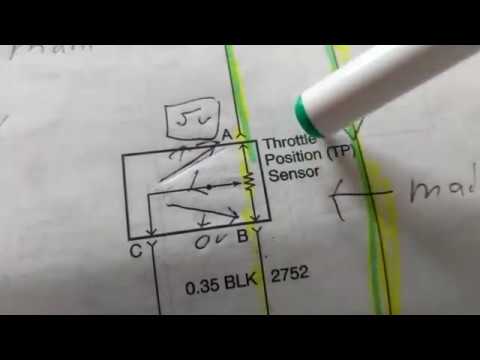
THROTTLE POSITION SENSOR explanation for wiring diagram

How Do You Test A Throttle Body With A Multimeter

Throttle Position Sensor Wire Diagram 4 | Manual E-Books - Throttle